Redirecting input to output
The simpliest signal chain that one can construct is connecting the input audio signal to the output.
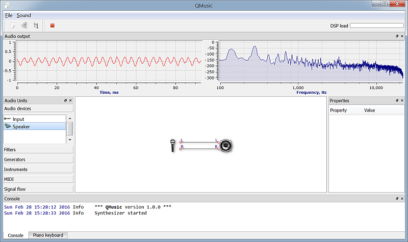
When running this circuit, the audio input (e.g. microphone) is redirected to the output (e.g. speaker) without and modification. Signal waveform and its spectrum is shown in the Audio output panel.
Low-pass filtering
We can make the circuit a bit more interesting by introducing some filtering of the input signal before sending it to the output. In the Filters group of the Audio Units panel there is LP/HP Filter that we can use. This is a simple low-pass or high-pass filter. We will need two of those since we are dealing with a stereo signal.
To control the filters cut-off frequency we will be using a slider unit that can be found in the Signal flow group. When dropping the slider onto the working canvas check its properties. We want to change its label to be Cut-off and the range of values from say 10 to 10000 (Hz), which represents the range of frequencies we want to operate in.
Connect the slider's output to the f inputs of the both filters.
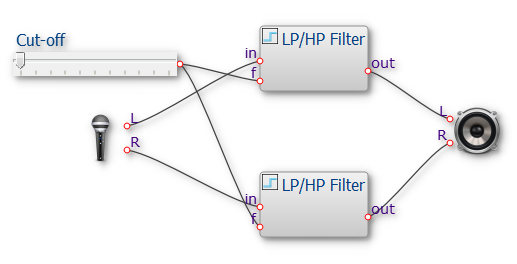
Now when you run this circuit you can play with the slider to filter the audio in real-time.
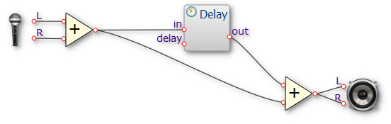
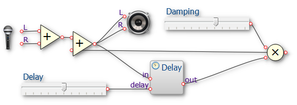
Making an echo
We can create a simple echo effect by introducing a delay on the audio signal line and then mixing the original signal with the delayed one together. This will create a "signle reflection" echo effect.
Here to simplify the circuit we add together left and right samples of the input to create a monophonic signal using the Added unit. Then the signal goes into a delay line set to 100ms.
If we want to create a "multiple reflection" echo effect we have to loop the delayed signal back to the input recursively. Such a feedback look can actually make the signal chain unstable and turn it into a generator. To avoid this we will have to damp the signal we feed back into the input. To do so we can for example multiply it with a value less then 1, say 0.5.
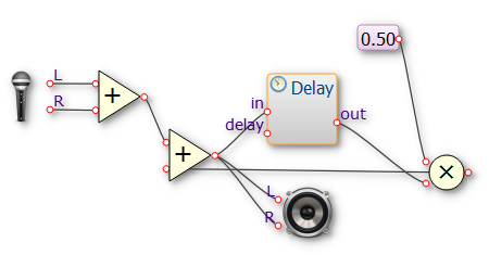
We can make the circuit even more flexible by adding sliders to control the delay time and the damping. The Delay audio unit has a second input called 'delay', which accepts a delay time fraction (value in 0..1 range) of the total delay set via the unit's properties panel. Now, if we set the total delay to 1000ms and add the slider to output a value in 0..1 range we can control the delay within 0..1s range with our slider. We can do the same for the damping factor.
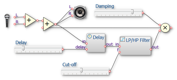
We can make the echo effect even more realisting by applygin a filtering on the delayed signal. Low-pass filter can be used here for example.
<< Back to the front page